2019/10/29

Position Fix: Rho-Rho, Rho-Theta, Theta-Theta position determination

In General Navigation, when talking about position fixes, one can differentiate between: Rho-Rho, Rho-Theta and Theta-Theta position determination types. The importance of this kind of position fixing have evolved with the appearance of a distance measuring equipment (DME)-based aircraft navigation techniques (DME/DME). The newly developing system is overtaking the GNSS in the next decade due to the GNSS’s weak signal and possible disruption disadvantage. To start with the basics, one can define Rho as a Greek letter R, which stands for range. Theta is an angle, thus a Rho-Rho fix is made from two ranges, a Rho-Theta fix is a fix made from an angle and so on.

Rho-Rho method:
The goal of the position determination with the Rho-Rho method is to find the aircraft’s position in 2D coordinate system, with the help of beacon’s in the range of their signal. The R-R technique requires only two range/distance measurements for a fix. [1]
To have a sufficiently correct and acceptable position, at least two beacon’s signal is needed to be located. The circle of the two will define two points in space (Figure 1.) but only one of them is showing the true position of the aircraft. In reality, if the aircraft is flying from a departing city to a destination, with a given heading, it is obvious which of these two points is determining the actual position of the aircraft. In other, uncertain situations this can be also resolved by tuning into a third DME or tuning into a VOR station. [2]

Ambiguity of DME position fix
The R-R method works the best for incoming signals perpendicularly to each other, and has the biggest error, if aligned in a line. This is illustrated by the following figures.
Beacons are displaced with right angle relative to each other
Beacons are displaced almost in line, highest error
It is also important to note that reliability problems may occur when using the R-R method for navigation in the vicinity of the airport at low altitudes, due to the line of sight problem.
Defining the expression: Dilution of Precision (DOP) will determine this reliability problem. It is an error occurring in all positioning systems. Since, each position line is subjected to errors, the DOP encounters only the influence of the geometry.

Rho-Rho-Rho method:
By having 3 range measurements from 3 different sources (satellites for GPS), we can determine also 2D position. (To have 3D position, 4 satellites are necessary)
Illustration of this kind of position fix is shown on the next figure.
In an RNAV mode using multiple DME, inaccuracy can be due to inability to confirm that the aircraft is within the Designated Operational Coverage (DOC) area of the DMEs because of identification problems.

Rho-Theta method:
VOR/DME position fixing is a typical example, used in VOR/DME-based Area Navigation System. The VOR/DME Area Navigation system has its own VHF NAV tuner and the system itself tunes the DME stations providing the best angular position lines. (When operating in the dead reckoning mode, data used are: TAS from the Air Data Computer; heading from the aircraft compass; the last computed W/V.) In a VOR/DME-based Area Navigation System, the crosstrack distance, alongtrack distance and angular course deviation information are provided.
One of the functions of the computer in a basic RNAV system is to transfer the information given by a VOR/DME station into tracking and distance indications to any chosen Phantom Station/waypoint. A "phantom station" is created by setting the distance (Rho) and the bearing (Theta) of the waypoint from a convenient VORTAC in the appropriate windows of the waypoint selector. A series of these "phantom stations" or waypoints make up an RNAV route.
Illustration of a phantom station [EASA]
Theta-Theta method:
Intersection from two VOR bearings:


To sum it up, in an RNAV system, the Rho-Rho combination of external reference will give the most accurate position. Rho is the Greek letter ρ, which stands for range. Θ Theta is an angle. Thus a Rho-Rho fix is made from two ranges (e.g. DME/DME) and a Rho-Theta fix is a fix made from a range and an angle (e.g. VOR/DME).
  • R-R uses distance/range from two sources for position determination,
  • R-T uses VOR/DME for position determination,
  • T-T uses bearings from two VOR stations.


Sources: 
Picture references: Attitude and Navigation Systems, Lecture notes, Warsaw University of Technology, www.daas.meil.pw.edu
[1]     - Myron Kayton, Walter R. Fried, Avionics Navigation Systems, pp.164.
[2]     - David Wyatt, Mike Tooley, Aircraft Communications and Navigation Systems, 2007

2019/10/11

Dead Reckoning (DR) position determination

DR position is an estimated position of the aircraft based on initial data (time elapsed, wind direction/velocity, heading, airspeed) that is used when overflying areas with no radio navigation coverage, or with no visual checkpoint available.

Positioning in dead reckoning navigation is obtained by adding translation/displacement vectors.

The next new position using the aircraft’s speed and course being calculated is the DR position. Correcting the DR position for crosswind, steering error results in an estimated position (EP). INS develops a very accurate EP. A line joining the last known position and the actual DR position is an estimated track, which differs from the actual track depending on the accuracy.

Accuracy of DR position depends on the following factors:
  • flight time since last known position update,
  • difference between actual and forecasted wind,
  • accuracy of the forecasted wind,
  • accuracy of heading (steered HDG), airspeed and TAS,
  • pilot skill and navigation accuracy flown.
DR technique is also used when operating using RNAV and the there is no signal received from either VOR or DME. Then the system selects the DR mode for a short time, based on the last computed values. The RNAV is trying to update the aircraft’s position based on the current TAS (from Air Data Computer) and HDG (from compass).

To sum it up, dead reckoning is an algorithm used to extrapolate entity states, used in modern navigation methods.

2019/08/15

Importance of Control Engineering - Inner/Outer Loops

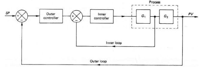
Here is a block diagram that I've just found during my ATPL preparation for Instrumentation subject. I'd never thought of ever writing about any topic related to Control in Aerospace, as it wasn't my favorite subject at university, however it made me think...
Autopilot Block diagram [AviationExam]
This is a representation of the basic autopilot operating principle including the Outer and Inner Loops. To understand the principles, let's see a bit of theory to understand what do they actually mean.

Inner Loop:
The "primitive/dumb" one, it's stabilizing and maintaining pitch, roll and yaw. The most basic system of an autopilot that provides only stabilization function consisting in controlling movements around the center of gravity of the aircraft is within the inner loop.
General structure of Inner Loop

Example of a typical Inner Loop Control System
Outer Loop:
Provides the autopilot with navigation (guidance) function. It adds the intelligence to the process (e.g. tracking a radial, holding a speed, climbing a VNAV path) The outer loop tells the inner loop what pitch, roll or yaw to hold for the maneuver, then the inner loop executes this. All the "intelligence" involved is mainly done in this loop.
Examples of outer loop autopilot operating modes:

Roll modes:
  • HDG (Select & Hold)
  • Nav Track (Track Hold)
  • VOR/LOC (Capture & Track)
  • Lateral Navigation (LNAV)
  • FMS Lateral Navigation

Pitch (flight path) modes:
  • Altitude (Select & Hold)
  • IAS/Mach (Hold)
  • Level change
  • Altitude Acquire (Capture)
  • Vertical speed
  • Glideslope (Capture & Track)
  • Vertical Navigation (VNAV)
  • FMS Vertical Navigation
  • Flare
  • FPAH (Flight Path Altitude Hold)

Combines Roll and Pitch modes:

  • Approach
  • Go-Around
  • Control Wheel Steering (CWS)

    Cascade Control System:
    The cascade control system includes a second feedback loop. Cascade control gives an improvement over single-loop control handling disturbance inputs. The effects of cascade control system are an increase in the system bandwidth and a reduction in the sensitivity to disturbances entering the inner loop.
    Cascade Control System structure
    Ok, so what's the connection with all these simple theory and my past university assignment?
    Back in the days, I had to create a project in which the task was the following:

    Project description:
    To generate a cascade control loop for the given transfer function of an aircraft system using PID controllers. The given transfer function is:

    The control variables are pitch and altitude.
    By controlling the measurements of these two variables and combining them using the control system to design, attitude reading is obtained. The general structure of the whole cascade control system for this project is presents in the next figure.
    Inner Loop:
    The main role of this part of the system is to control the changes in pitch measurements which are obtained from the gyroscope. As shown in the figure the errors in pitch are reduced by comparing it to the desired value.
    The structure of the inner loop

    Outer Loop:
    The main goal of this part of the system is to feed the inner loop with the corrected value of the altitude so it could be combined with the aircraft system transfer function to obtain an accurate output.

    The structure of the outer feedback loop (Cascade)
    The simulation was performed for different altitude inputs, and the outputs presented  on graphs. (Aircraft Altitude Change, Aircraft Pitch Angle - Desired Vs Actual, Actual Pitch Angle, Error of Altitudes for 100 and 200m, Error of the Elevator Deflection fr 100 and 200m)

    A cascade control system was generated to control the motion of the actuator that is used to deflect the elevator in order to obtain a desired altitude change. The inner loop minimizes pitch errors and feeds the actual pitch value to the outer loop to obtain an accurate reading.

    Do you see the connection between an engineering approach for an automation system that is employed on aircraft and the importance of understanding Control theories?
    All these are connected. Whether it's engineering or piloting, you're going to meet with Control and basic Control theories everywhere, where automation is applied. Respect Control. Accept it, and learn the basics to conveniently tackle the obstacles in your career.

    2018/08/05

    Why point is used instead of decimal in CS documents (EASA)

    You may wonder why EASA uses "·" instead of "," symbol for decimals in the CS Certification Specification documents (e.g. CS-23, CS-25, ...).To clearly understand the problem, see this example:

    CS-25.355 (e)
    "(3) VF may not be less than –
         (i) 1·6 VS1 with the wing-flaps in take-off position at maximum take-off weight;"

    The reason is that they use the spoken name of the symbol, such as "point" instead of decimal. In our example: one-point-six times the stall speed in a specified configuration. Don't confuse it with multiplication.

    On the other hand, in ICAO radiotelephony the "," and the "." symbol must be pronounced as "decimal", and not as "point", for avoiding confusion. (See ICAO Annex 10, Volume II.)

    2018/04/17

    Trent 1000 issues and ETOPS

    Both the FAA and the EASA released an Airworthiness Directive regarding the new, Trent 1000 engine, specially designed for Boeing 787 family.
    The engine is a Rolls-Royce, 3-shaft, high bypass ratio turbofan engine, capable of maximum thrust: 265–360 kN. When experiencing an inflight shut down, the other engine is operated on a higher load, at its maximum continuous thrust, during which the intermediate compressor blades may be exposed to severe vibrations. This, in an ETOPS operation could fail, resulting in an intermediate pressure turbine blade (IPTB) cracking/fracture.


    According to the FAA Directive:
    "Over the past year, we have been aware of several engine failures of Trent 1000 Package C engines due to failed compressor and turbine blades and seals. Package C engines are Rolls-Royce plc (RR) Trent 1000-A2, Trent 1000-AE2, Trent 1000-C2, Trent 1000-CE2, Trent 1000-D2, Trent 1000-E2, Trent 1000-G2, Trent 1000-H2, Trent 1000-J2, Trent 1000-K2, and Trent 1000-L2 turbofan engines. During that same period, under the management programs for those engine issues, we have been aware of numerous reports of engine inspection findings of cracked blades resulting in unscheduled engine removals. Boeing reported to the FAA that the engine manufacturer recently determined that intermediate pressure compressor (IPC) stage 2 blades have a resonant frequency that is excited by the airflow conditions existing in the engine during operation at high thrust settings under certain temperature and altitude conditions. The resultant blade vibration can result in cumulative fatigue damage that can cause blade failure and consequent engine shutdown. In the event of a single engine in-flight shutdown during the cruise phase of flight, thrust on the remaining engine is normally increased to maximum continuous thrust (MCT). During a diversion following a single engine shutdown under an ETOPS flight, the remaining engine may operate at MCT for a prolonged period, under which the IPC stage 2 blades would be exposed to the resonant frequency condition. Therefore, an ETOPS diversion will put the remaining engine at an operating condition that would significantly increase the likelihood of failure of the remaining engine. In addition, if the remaining engine already had cracked IPC stage 2 blades, the likelihood of the remaining engine failing will further increase before a diversion can be safely completed."

    In the EASA's Directive:
    "An occurrence was reported where, following N2 vibration and multiple messages, the flight crew performed an engine in-flight shut-down (IFSD) and returned to the departure airport, landing uneventfully. The post-flight borescope inspection of the engine revealed an intermediate pressure turbine blade (IPTB) missing at the shank. Analysis shows that this kind of failure is due to sulphidation corrosion cracking.
    This condition, if not detected and corrected, could lead to IPTB shank release, possibly resulting in an IFSD and consequent reduced control of the aeroplane.
    To address this potential unsafe condition, RR issued Alert NMSB Trent 1000 72-AJ575 to provide instructions for engine removal from service when any IPTB with a high level of sulphidation exposure is identified by corrosion fatigue life (CFL) model. Consequently, EASA issued AD 2017-0056 to require removal from service of certain engines, to be corrected in shop.
    Since that AD was issued, prompted by further occurrences and analyses, it has been decided that, to reduce the risk of dual IFSD, a new cyclic life limit must be applied to certain engines, which determines when an engine can no longer be installed on an aeroplane in combination with certain other engines.
    For the reason described above, this AD requires de-pairing of the affected engines. This AD is considered an interim action and further AD action may follow."


    What does ETOPS stand for?
    It is an extended range operations with two-engined aeroplanes.
    "In commercial air transport operations, two-engined aeroplanes shall only be operated over routes that contain a position further from an adequate aerodrome that is greater than the threshold distance determined in accordance with CAT.OP.AH.140, if the operator has been granted an ETOPS approval by the competent authority."

    For an airline in order to..."obtain an ETOPS operational approval from the competent authority, the operator shall provide evidence that:
    (a) the aeroplane / engine combination holds an ETOPS type design and reliability approval for the intended operation;
    (b) a training programme for the flight crew and all other operations personnel involved in these operations has been established and the flight crew and all other operations personnel involved are suitably qualified to conduct the intended operation;
    (c) the operator‟s organisation and experience are appropriate to support the intended operation; and
    (d) operating procedures have been established."
    There is also a minima requirement when planning the alternate aerodrome.
    In case of performance class A aeroplanes (seating configuration of 20 or more, MTOM of 45360 kg or more), this distance flown is 60 minutes at one-engine-inoperative (OEI),
    class A aeroplanes (seating configuration of 19 or less, MTOM less than 45360 kg), this distance flown is 120 minutes, or subject to approval by the competent authority, up to 180 minutes for turbo-jet airplanes, at OEI.


    Summarizing it, the FAA AD requires revising the AFM to limit ETOPS operation and the EASA's requirements are de-pairing the affected engines.

    Sources:

    2017/09/04

    Heat Conduction Equation


    This blog is intended to summarize the Heat Conduction Equation and its derived forms in different analyses. Prerequisite to this article is basic knowledge in Heat Transfer and therefore explanation of the used symbols in the equations, as well as explanation of formulas is excluded from this writing.

    Heat conduction in a medium is a dimensional process, depending on the number of dimensions in which it acts. It also varies with time, however, based on the assumptions of steady state (when the temperature does not change with time), or unsteady state (transient), one can have two approaches.
    The following flowchart is intended to help distinguishing the states and to select the best suited case with formulas provided.

    Steady: no change with time at any point,
    Transient: variation with time and position.
    (Lumped system: variation with time but not with position.)
    Figure 1. Conduction main flowchart
    In the Steady State Conduction the temperature is independent of the time change. One can further distinguish one dimensional heat transfer, where the temperature change varies only in one direction. We can talk about multiple dimensions as two- and three-dimensions, which are calculated in a different manned.
    In case of 1D conduction, the function depends only on the x dimension, therefore the partial derivatives are replaced by ordinary derivatives.

    General form of Heat Conduction Equation (HCE), in rectangular coordinates is called: Fourier- Kirchoff equation:
    The general HCE equation can be derived into different special forms, depending on the assumptions and the used boundary conditions.

    Boundary and initial conditions for HCE:
    There are 4 main boundary conditions used or HCE, these are:


    1. Temperature of the surface (TS) at any time is given,
    2. Heat flux (qS) on the boundary at any time is given,
    3. Fluid temperature distribution (Tf) around the system and convective heat transfer (h) between the system and the fluid is given:
    4. Balance of heat fluxes on both sides of the boundary is given, (applied between 2 solids of different thermal conductivity)
    Figure 2. Steady State Conduction flowchart

    Figure 3. Transient Conduction flowchart


    Figure 4. Transient Conduction computation flowchart


    References:
    ·         Yunus A. Cengel – Heat Transfer – A practical approach, second ed., 2003

    ·         Heat Transfer lecture notes – Maciej Jaworski, Warsaw, 2016

    2017/08/15

    Hyperbolic and diagonalizable matrices

    HOW TO DETERMINE IF THE SYSTEM OF LINEAR EQUATION IS HYPERBOLIC?

    When dealing with system of Partial Differential Equations (PDE) one may have to determine if the matrix A, satisfying the equation is whether hyperbolic or not. In order to determine if a system of PDE is hyperbolic, one must determine if the matrix is diagonalizable.

    To open full text: click here

    Reference: Advanced Computational Fluid Dynamics, Lecture notes - Jacek Rokicki, 2014

    2017/05/01

    Finite Difference method

    In this post, you can see how the analysis of the accuracy of the given finite-difference formula is achieved for a first order derivative case.
    In order to solve ODE problems or Partial Differential Equations (PDE) by system of algebraic equations, there are certain methods available. The Finite Difference method is probably the oldest numerical method that is used.
    Figure 1. Numerical solution flowchart
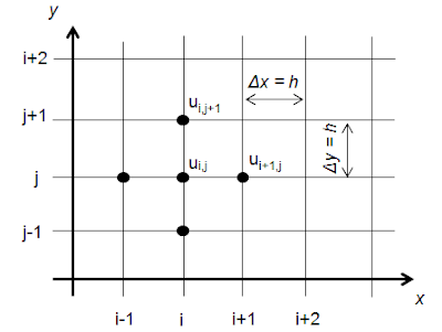
    It is recommended to choose a uniformly distributed grid size, having the size of X and Y components the same, due to memory limitations.

    Suppose that function U(x) is given as such:
    Figure 2. Selection of points on a function
    One would like to estimate the first derivative of the function U(x) at some point x(j). The value of the neighboring nodes are given: uj = u(xj), uj+1, uj-1, where xj = j*h.
    Figure 3. 2D final difference grid
    Having a differential equation for a 2D, compressible flow, non-viscous, non-stationary:
    One takes the definition of the first derivative:
    If the discretization is small enough (Δx), it will approximate the value of the function as:

    Similarly to Equation (1.2) one can propose different algebraic formulas for determining the determinant for a given point of the function.
    It is important to notice that Equations (1.2) and (1.4) are 1st order accurate, meanwhile (1.5) is 2nd order accurate.
    Figure 4. Different approximations
    From the above plot, it is clearly visible that out of the 3 different formulas for finding the derivative at a given point Xj, the line that is closest to the tangent point at that point is III. This is the so called central difference and is more accurate that the other, forward difference one. The errors can be determined simply by the Taylor expansion.
    Similarly to Equation (1.3) the following algebraic equations can be written:
    One can conclude that the finite difference formula has order of accuracy n and is proportional to hn for small values of step size h. The central difference is 2nd order accurate and higher order terms are resulting in lower accuracy, therefore the 2nd order formula works best for calculating ODE-s and PDE-s.
    Other method for deriving finite difference formulas (with different accuracy) for a given differential order remains a problem to solve.


    To download full text in PDF: click here
    Reference: Computational Fluid Dynamics, Lecture notes - Jacek Rokicki, 2014