2019/10/29

Position Fix: Rho-Rho, Rho-Theta, Theta-Theta position determination

In General Navigation, when talking about position fixes, one can differentiate between: Rho-Rho, Rho-Theta and Theta-Theta position determination types. The importance of this kind of position fixing have evolved with the appearance of a distance measuring equipment (DME)-based aircraft navigation techniques (DME/DME). The newly developing system is overtaking the GNSS in the next decade due to the GNSS’s weak signal and possible disruption disadvantage. To start with the basics, one can define Rho as a Greek letter R, which stands for range. Theta is an angle, thus a Rho-Rho fix is made from two ranges, a Rho-Theta fix is a fix made from an angle and so on.

Rho-Rho method:
The goal of the position determination with the Rho-Rho method is to find the aircraft’s position in 2D coordinate system, with the help of beacon’s in the range of their signal. The R-R technique requires only two range/distance measurements for a fix. [1]
To have a sufficiently correct and acceptable position, at least two beacon’s signal is needed to be located. The circle of the two will define two points in space (Figure 1.) but only one of them is showing the true position of the aircraft. In reality, if the aircraft is flying from a departing city to a destination, with a given heading, it is obvious which of these two points is determining the actual position of the aircraft. In other, uncertain situations this can be also resolved by tuning into a third DME or tuning into a VOR station. [2]

Ambiguity of DME position fix
The R-R method works the best for incoming signals perpendicularly to each other, and has the biggest error, if aligned in a line. This is illustrated by the following figures.
Beacons are displaced with right angle relative to each other
Beacons are displaced almost in line, highest error
It is also important to note that reliability problems may occur when using the R-R method for navigation in the vicinity of the airport at low altitudes, due to the line of sight problem.
Defining the expression: Dilution of Precision (DOP) will determine this reliability problem. It is an error occurring in all positioning systems. Since, each position line is subjected to errors, the DOP encounters only the influence of the geometry.

Rho-Rho-Rho method:
By having 3 range measurements from 3 different sources (satellites for GPS), we can determine also 2D position. (To have 3D position, 4 satellites are necessary)
Illustration of this kind of position fix is shown on the next figure.
In an RNAV mode using multiple DME, inaccuracy can be due to inability to confirm that the aircraft is within the Designated Operational Coverage (DOC) area of the DMEs because of identification problems.

Rho-Theta method:
VOR/DME position fixing is a typical example, used in VOR/DME-based Area Navigation System. The VOR/DME Area Navigation system has its own VHF NAV tuner and the system itself tunes the DME stations providing the best angular position lines. (When operating in the dead reckoning mode, data used are: TAS from the Air Data Computer; heading from the aircraft compass; the last computed W/V.) In a VOR/DME-based Area Navigation System, the crosstrack distance, alongtrack distance and angular course deviation information are provided.
One of the functions of the computer in a basic RNAV system is to transfer the information given by a VOR/DME station into tracking and distance indications to any chosen Phantom Station/waypoint. A "phantom station" is created by setting the distance (Rho) and the bearing (Theta) of the waypoint from a convenient VORTAC in the appropriate windows of the waypoint selector. A series of these "phantom stations" or waypoints make up an RNAV route.
Illustration of a phantom station [EASA]
Theta-Theta method:
Intersection from two VOR bearings:


To sum it up, in an RNAV system, the Rho-Rho combination of external reference will give the most accurate position. Rho is the Greek letter ρ, which stands for range. Θ Theta is an angle. Thus a Rho-Rho fix is made from two ranges (e.g. DME/DME) and a Rho-Theta fix is a fix made from a range and an angle (e.g. VOR/DME).
  • R-R uses distance/range from two sources for position determination,
  • R-T uses VOR/DME for position determination,
  • T-T uses bearings from two VOR stations.


Sources: 
Picture references: Attitude and Navigation Systems, Lecture notes, Warsaw University of Technology, www.daas.meil.pw.edu
[1]     - Myron Kayton, Walter R. Fried, Avionics Navigation Systems, pp.164.
[2]     - David Wyatt, Mike Tooley, Aircraft Communications and Navigation Systems, 2007

2019/10/11

Dead Reckoning (DR) position determination

DR position is an estimated position of the aircraft based on initial data (time elapsed, wind direction/velocity, heading, airspeed) that is used when overflying areas with no radio navigation coverage, or with no visual checkpoint available.

Positioning in dead reckoning navigation is obtained by adding translation/displacement vectors.

The next new position using the aircraft’s speed and course being calculated is the DR position. Correcting the DR position for crosswind, steering error results in an estimated position (EP). INS develops a very accurate EP. A line joining the last known position and the actual DR position is an estimated track, which differs from the actual track depending on the accuracy.

Accuracy of DR position depends on the following factors:
  • flight time since last known position update,
  • difference between actual and forecasted wind,
  • accuracy of the forecasted wind,
  • accuracy of heading (steered HDG), airspeed and TAS,
  • pilot skill and navigation accuracy flown.
DR technique is also used when operating using RNAV and the there is no signal received from either VOR or DME. Then the system selects the DR mode for a short time, based on the last computed values. The RNAV is trying to update the aircraft’s position based on the current TAS (from Air Data Computer) and HDG (from compass).

To sum it up, dead reckoning is an algorithm used to extrapolate entity states, used in modern navigation methods.

2019/08/15

Importance of Control Engineering - Inner/Outer Loops

Here is a block diagram that I've just found during my ATPL preparation for Instrumentation subject. I'd never thought of ever writing about any topic related to Control in Aerospace, as it wasn't my favorite subject at university, however it made me think...
Autopilot Block diagram [AviationExam]
This is a representation of the basic autopilot operating principle including the Outer and Inner Loops. To understand the principles, let's see a bit of theory to understand what do they actually mean.

Inner Loop:
The "primitive/dumb" one, it's stabilizing and maintaining pitch, roll and yaw. The most basic system of an autopilot that provides only stabilization function consisting in controlling movements around the center of gravity of the aircraft is within the inner loop.
General structure of Inner Loop

Example of a typical Inner Loop Control System
Outer Loop:
Provides the autopilot with navigation (guidance) function. It adds the intelligence to the process (e.g. tracking a radial, holding a speed, climbing a VNAV path) The outer loop tells the inner loop what pitch, roll or yaw to hold for the maneuver, then the inner loop executes this. All the "intelligence" involved is mainly done in this loop.
Examples of outer loop autopilot operating modes:

Roll modes:
  • HDG (Select & Hold)
  • Nav Track (Track Hold)
  • VOR/LOC (Capture & Track)
  • Lateral Navigation (LNAV)
  • FMS Lateral Navigation

Pitch (flight path) modes:
  • Altitude (Select & Hold)
  • IAS/Mach (Hold)
  • Level change
  • Altitude Acquire (Capture)
  • Vertical speed
  • Glideslope (Capture & Track)
  • Vertical Navigation (VNAV)
  • FMS Vertical Navigation
  • Flare
  • FPAH (Flight Path Altitude Hold)

Combines Roll and Pitch modes:

  • Approach
  • Go-Around
  • Control Wheel Steering (CWS)

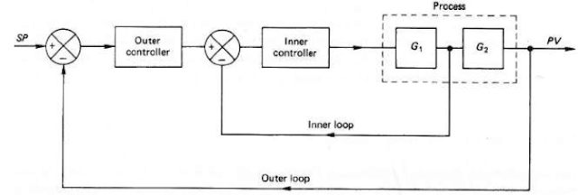
    Cascade Control System:
    The cascade control system includes a second feedback loop. Cascade control gives an improvement over single-loop control handling disturbance inputs. The effects of cascade control system are an increase in the system bandwidth and a reduction in the sensitivity to disturbances entering the inner loop.
    Cascade Control System structure
    Ok, so what's the connection with all these simple theory and my past university assignment?
    Back in the days, I had to create a project in which the task was the following:

    Project description:
    To generate a cascade control loop for the given transfer function of an aircraft system using PID controllers. The given transfer function is:

    The control variables are pitch and altitude.
    By controlling the measurements of these two variables and combining them using the control system to design, attitude reading is obtained. The general structure of the whole cascade control system for this project is presents in the next figure.
    Inner Loop:
    The main role of this part of the system is to control the changes in pitch measurements which are obtained from the gyroscope. As shown in the figure the errors in pitch are reduced by comparing it to the desired value.
    The structure of the inner loop

    Outer Loop:
    The main goal of this part of the system is to feed the inner loop with the corrected value of the altitude so it could be combined with the aircraft system transfer function to obtain an accurate output.

    The structure of the outer feedback loop (Cascade)
    The simulation was performed for different altitude inputs, and the outputs presented  on graphs. (Aircraft Altitude Change, Aircraft Pitch Angle - Desired Vs Actual, Actual Pitch Angle, Error of Altitudes for 100 and 200m, Error of the Elevator Deflection fr 100 and 200m)

    A cascade control system was generated to control the motion of the actuator that is used to deflect the elevator in order to obtain a desired altitude change. The inner loop minimizes pitch errors and feeds the actual pitch value to the outer loop to obtain an accurate reading.

    Do you see the connection between an engineering approach for an automation system that is employed on aircraft and the importance of understanding Control theories?
    All these are connected. Whether it's engineering or piloting, you're going to meet with Control and basic Control theories everywhere, where automation is applied. Respect Control. Accept it, and learn the basics to conveniently tackle the obstacles in your career.